My "Musicbox" Car MP3 Player


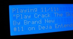 |
Now in blue : ) I just can't get full-view photos of it to come out right... It looks like this though, except twice as wide. |
More photos
(Note: that beautiful 7x7x1.75" case was custom-designed by Dave Helander, and named "Bantam II")
Updates / Status
Introduction
How to Make Your Own
Features of My Musicbox
LCD Information
Parallel Port Information
Connecting the LCD to the Computer
Connecting the Computer to the Car Stereo
Powering the Computer
Pitfalls
References
Updates / Status
Quick status, May 20, 2008: This musicbox system has been replaced by my iPhone. The musicbox served me well for about 5 years, but now, to me, the iPhone is a far cooler and more convenient way to listen to music and podcasts in my car.
Quick status, May 26, 2004: I finally found a blue 4x40 character parallel-interface LCD, from crystalfontz.com, for about $50 -- same as the green ones. Oh, and the musicbox now uses an infrared remote control instead of / in addition to the keyboard. Very cool.
Read the updates page for more. And check out all the photos I've taken.
Introduction
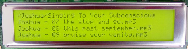
I have a 40x4 character LCD screen connected to the parallel port
on my Pentium 233mmx system
VIA Eden 600MHz system, and I wrote a
perl script to let me choose mp3s to play, displaying my options on the
LCD. I use a Gyration
wireless (radio) keyboard for the input; it's very small, thin,
and black. The box runs Slackware Linux, and is configured to
boot directly to a sparse startup script that just loads USB and sound
modules, and then runs the music script. It doesn't run any of
the normal init scripts, doesn't go into multiuser mode, and doesn't
create any extra terminals. Current boottime, from ignition to
music playing, is 27 seconds.
Probably the most important feature of my particular design is that it is interactive at the typed-character level: when you want to access a given band, you type just the first letter or two of that band's name, and the system responds immediately, "homing in" on the band as you type more. This makes it possible to select and play music from any band among a library of hundreds, usually in just 3 or 4 key presses. I think this is infinitely better than scrolling through hundreds of bands (though my script provides scrollability, as well.) The second most important (and cool) feature is the random-play modes: when I hit the tick key, it plays a random album from the hard drive, and when I hit the | key, it plays 100 random songs from all over the hard drive.
The total cost of this project was about $300 $450. The computer is
an old Pentium-I 233mmx that I already had a VIA EPIA ME6000, with
built-in everything including 600MHz cpu, for about $120. I paid about $120 for
a 40 gigabyte IBM notebook hard drive, $100 for the Gyration keyboard
(as part of a keyboard/mouse/mousecharger package, so the keyboard itself
isn't actually that expensive), $30 for the LCD screen, and various smaller
amounts for things like cables, potentiometers, resistors, etc.
How to Make Your Own
This project is built on completely free software: the Slackware Linux operating system, the mpg321 music player, and a perl script that I wrote which runs everything. So you can build your very own musicbox. Just follow the instructions here to set up the computer, and then come back to this page to learn how to do the power and wiring.
And don't hesitate to contact me if you need any help!
Features of My Musicbox
- All keymappings are user-adjustable.
- Direct-text input to select folders/tracks (ex. pressing g will display G. Love, Genesis, Get Up Kids, and Green Day, pressing ge will display Genesis and Get Up Kids, pressing get will display only Get Up Kids)
- Arrow keys scroll the folder/songlist and PageUp/Down will jump 4 folders/songs.
- Plays a random album from the hard drive when the tick key is pressed; plays a different one when you press it again. This is one of my favorite features. And pressing the | key will play 100 randomly-chosen songs from all over the hard drive.
- Displays Artist/Title/Album of currently playing song.
- Allows you to play/enqueue an entire folder, or play/enqueue one song at a time. Enqueueing can be done while music is playing; or, pressing Enter on an album in the music library during playback will stop the current song, clear the playlist, and play your new selection(s).
- Playlist is saved to disk so you can reboot, etc and still have it. The position in the currently playing song is also saved (along with the current volume) across reboots, so it resumes right where you were like a normal car stereo.
- Optionally shows cpu idle percentage and free memory in a corner of the LCD.
- Remembers your position as you scroll through your list of bands (an essential feature for large music collections).
- It's pauseable! This was tricky to figure out since I'm running the mp3 player in a forked detached process. But pause is essential, and it's working.
- Seeks within tracks, and skips forwards and backwards in your playlist.
- Playlist editor lets you enqueue folders/songs, move songs up or down in the playlist, remove songs from the playlist, or jump directly to a specific song.
- Built-in volume control including mute.
- System startup time, from power-on to music coming out the speakers, is ~30 seconds. Only about 10 of that is linux; the power-on and POST process takes 20 seconds.
- Emulates a "normal" car stereo as much as possible: plays music automatically when you start the car, shuts off automatically when you turn the car off, and resumes playing at the same spot in the same song as when you last turned the car off.
- Has a built-in shell prompt, with output on the LCD screen, and a command history. TODO: figure out how to redirect STDERR to the LCD in addition to STDOUT; for some reason, the normal bash-redirection 2>&1 isn't working.
- Handy online help -- just press F1 to see what all the features and keys are. And the key bindings are all user-definable by simply setting them in beginning of the script.
- Displays your MP3 count, album count, and space used.
LCD Information
My LCD is a Seiko M4024 4x40 character display with an LCD backlight. It has two built-in HD44780 chips to control the screen (one chip can address 2 rows of 40 characters). I got it from mpja.com for $35. Note: different LCD screens are not, not, NOT pin-compatible with eachother, not at all, not by a long shot, not even from the same manufacturer. I have 2 Seiko 40-wide displays that are completely different. So don't believe any websites that say you can use their pinouts with your LCD, unless you have a datasheet for your LCD that agrees with their pinout. Anyway, my musicbox will work with any 4x40 character parallel-interface LCD that uses the HD44780 controller chip. Here is the pinout, direct from the datasheet:
LCD Pin   Function   More Info
-------------------------------------------------------------------
 1        DB7        Data bus
 2        DB6        signals
 3        DB5        7 to 0
 4        DB4
 5        DB3
 6        DB2
 7        DB1
 8        DB0
 9        E1         Enable 1 -- enables rows 1 and 2 on the LCD
10        R/^W       HI to read from LCD, LO to write to it
11        RS         Register select (data or instruction)
12        VLC        LCD contrast voltage
13        VSS        Ground
14        VDD        +5V power
15        E2         Enable 2 -- enables rows 3 and 4 on the LCD
16        NC         No Connect
This LCD has 16 holes on one end, arranged in an 2x8 matrix, for connecting all these signals. I bought a 2x13 header connector from mpja.com for 9 cents, and just snapped the extra pins off. Then I soldered that guy onto the LCD. This seemed impossible at first because the pins are pretty close together -- or at least, if you're not very experienced with PCB soldering, they seem close together. But it turned out to be pretty easy. And since a computer's internal gameport connector uses a 2x8 header, I found a spare one and cut the header off. I connected that to my parallel port cable, so it's easy to connect and disconnect my LCD. Finally, the other end of the LCD has 2 pads marked A and C (or A and K) for the backlight's anode (+) and cathode (-). I soldered a molex connector onto here so that this too would be easy to connect and disconnect. You can see photos of all this right here.
Parallel Port Information
The standard parallel port pinouts are as follows. Note that the signals and numbers are standardized (i.e., yours should be the same), but the colors are not.
Parallel         Parallel
Port             Port       LCD
Pin              Function   Function   More Info
-------------------------------------------------------------------
 1 brown         ^C0        E1         Enable 1
 2 red           DB0        DB0        Data bus
 3 orange        DB1        DB1        signals
 4 yellow        DB2        DB2        0 to 7
 5 green         DB3        DB3
 6 blue          DB4        DB4
 7 purple        DB5        DB5
 8 white         DB6        DB6
 9 pink          DB7        DB7
10 red-black     NC
11 orange-black  NC
12 blue-black    NC
13 gray-black    NC
14 brown-white   ^C1        E2          Enable 2
15 green-white   NC
16 orange-white  C2         RS          Register Select
17 purple-white  NC
18 - 25          GND        GND         Ground all these


Ground pins:
18 brown-gray
19 orange-gray & red-gray
20 green-gray & yellow-gray
21 purple-gray & blue-gray
22 pink-gray & white-gray
23 green-black & blue-white
24 pink-black & yellow-black & purple-black
25 gray-white & yellow-white & red-white

Other No Connect wires:
gray-red, brown-red


The numbering for the parallel port male cable end is like this,
with the pins pointing "out of the page":

 ____________________________________
 \ 1                             13 /
  \                                /
   \ 14                        25 /
    ------------------------------
Connecting the LCD to the Computer
I get my +5V from the motherboard power connector; you can also find it in the gameport or USB connector. Note that VLC (the contrast voltage) needs to be negative. I get this from the motherboard power connector's -5V (which is more like -7V on my system...). I have 920 ohms of resistance between the -5V and the VLC pin on the LCD, and that gives me good contrast. For both the +5V and -5V, I spliced into the parallel port connector's cable (on pins 11 and 13) to send those voltages to the LCD. Make sure you actually sever the wires connected to pins 11 and 13 on the motherboard-side of the connector; you don't want to send those voltages into the motherboard.
LCD Pin               Connects To
-------------------------------------------------------------------
 1 DB7                Parallel Port 9, DB7 (pink)
 2 DB6                Parallel Port 8, DB6 (white)
 3 DB5                Parallel Port 7, DB5 (purple)
 4 DB4                Parallel Port 6, DB4 (blue)
 5 DB3                Parallel Port 5, DB3 (green)
 6 DB2                Parallel Port 4, DB2 (yellow)
 7 DB1                Parallel Port 3, DB1 (orange)
 8 DB0                Parallel Port 2, DB0 (red)
 9 E1                 Parallel Port 1, ^C0 (brown)

10 R/^W               Ground, because I don't want to
                      read from the LCD, just write to it

11 RS                 Parallel Port 16, C2 (orange-white)

12 VLC                Approx. -1V, obtained by sending the PC's
                      -5V through parallel port pin 13, and then
                      through 920 ohms

13 VSS                Parallel Port 18-25 (which are all Ground)
14 VDD                +5V, sent on parallel port pin 11
15 E2                 Parallel Port 14, ^C1 (brown-white)
16 NC                 No Connect

A (backlight anode)   A 25 ohm potentiometer, which then connects
                      to +5V, sent on parallel port pin 11

C (backlight cathode) Parallel Port 18-25 (which are all Ground)
Note: I've since set up a second system to use for testing, which required making a second parallel-port-to-LCD cable. You can view the pin information for that cable here.
Connecting the Computer to the Car Stereo
I had to buy a special adapter (Kenwood CA-C1AX) to give my head unit an aux input, and I discovered that this $20 adapter can be easily home-made. Just follow these instructions. Anyway, I have a pair of RCA cables carrying the signal from my sound card (in the car's hatch) up to the head unit, into this adapter, and that's how I get my musicbox to play through my car stereo.
Powering the Computer
Note: everything in the following diagram is optional, except the car battery and the computer. Here's what you lose if you leave parts out:
- UPS battery and diode: necessary if you want the computer to not reboot
when you turn the engine over to start the car. (I.E., you turn the
computer on and let it boot up and start playing music BEFORE starting the
engine. Or you stall the engine, but the musicbox keeps playing.
In either case, when you start the engine, the computer will reboot unless
the UPS battery and diode are there.)
- RC circuit (diode, capacitor, resistor, transistor, top relay): necessary
if you want the computer to automatically save the playlist and current song position
when you turn the car off. Without these parts, the computer loses power
as soon as the car shuts off (when ACC goes low), so you must manually tell the
computer to save its state and shut off (by pressing a key; "!" by default) before
turning the car off.
- Bottom relay: necessary if you want the computer to turn on automatically
when the car turns on.
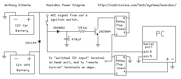
Note: not to scale. The UPS battery is about 1/5 the size of the car battery, and the relays are smaller than one cubic inch.
The computer is powered by a DC ATX power supply, the PW-70 from idotpc.com. (You can also use an AC inverter instead of a DC supply; I did for a few months.) When a car's ignition is turned "one click" into the accessory position, it turns on the accessory signal, which turns on other things like the stereo. I feed this accessory signal into a relay (an electrical switch) to turn the computer on. For the relays that I use, applying 12V across pins 1 and 5 causes pins 3 and 4 to be shorted. (For some reason, there's no pin 2.) I also have a second relay as part of an RC circuit that keeps the computer powered for about 11 seconds after the key is removed from the ignition. I send the car's accessory signal into the computer's serial port, and in my musicbox software, I detect when the accessory line turns off. This causes the computer to save the current playlist and song position to disk, and shut down nicely, before the power is cut. (The process of shutting down actually takes about 5 seconds.)
The second battery is a small sealed-lead-acid (SLA) battery taken out of a $40 APC UPS. It's there because a car's "12V" voltage sometimes sags a lot; for example it sags down to 9 or 10 volts during ignition. Computers are finicky about their 12V, and they reboot when it drops like that. By adding a second battery in parallel with the car's battery (and putting a big diode in between so the car doesn't steal the second battery's voltage too), I'm able to guarantee that there's always 12V available for the computer. So when I stop for gas and keep the music playing, the computer doesn't reboot when I start up the car again.
The RC circuit is just a timer: when the input signal (the car's ACC line) goes away, the capacitor slowly discharges through the resistor, keeping the transistor forward-biased and thus keeping the relay open, thus keeping the computer powered. It takes the capacitor 3*R*C seconds to discharge, so that's how long the power stays on. Using a 7.5 kilohm resistor and a 470 microfarad capacitor, that works out to 3 * (7.5 x 10^3) * (470 x 10^-6) = 10,575 x 10^-3 = about 10.6 seconds. I have the head unit and my amps switched by the same circuit, which means I can have the musicbox fade out the music before everything shuts off.
I have a small push-on-off SPST switch mounted near the head unit, so that I can forcibly kill the power if need be.
Here are the specs for the relays. They cost me 29 cents each, from mpja.com. You can see photos of one here. This is the description from mpja.com:
Product:		12VDC PC MT SPST RELAY
MFG:			OMRON

P/N:			G2R-1A4-ASI
COIL Voltage:		12VDC/270 Ohms
CONTACT RATINGS: 	10A/30VDC/250VAC
CONNECTION:		P.C. Mount. UL/CSA Listed.
L:			1-5/8"
W:			7/16"
H:			1"
WT:			.01

Stock No.:		13324 RL
Price:			$0.29
Pitfalls
-
LCD Pinouts. My first 3 LCD screens that I bought didn't come
with any pinout listings, and I made the mistake of believing all the
websites that say "all HD44780 chips are pin-compatible", and as a
result, my screens didn't work.
-
Control signals. These are the C0, C1, C2, C3 signals coming
out of the parallel port that you need to use for your Enable and RS signals
on your LCD. Which ones you'll use depends on the program you're using
to write to the parallel port. If you use the same program that I
did, then the pin connections that I listed will work.
-
Contrast voltage VLC. I read on many websites that this should be
grounded or should go through a "variable resistor" (potentiometer) to
+5V. If you do that, you get no output on your LCD whatsoever,
which is exactly what I got until I came across one obscure site that
mentioned that this voltage needs to be negative.
-
Soldering. My LCD didn't come with any handy wires or headers attached,
so I had to solder it all up. And the through-holes are very very close
together, so you have to be really careful not to use too much solder
and not to run any of them together.
-
Priveleges. You have to be root to write to the parallel port, but
XMMS wouldn't run for me as root until I uninstalled it and re-installed
it as root. (Note: I'm no longer using XMMS.)
-
Boot delays. On my system, if you don't have a "normal" (AT, or PS/2 with
an adapter to AT) keyboard plugged in, the POST process takes an extra 5 seconds.
Since I'm using a USB keyboard, I don't have any need for another one. But
5 seconds at boot is a long time when the total boot time is on the order of
30 seconds. So I took apart an old AT keyboard I had laying around, removed
the circuit board, wrapped it in electrical tape to cover all the solder points,
then stuck it inside the computer with the plug going out the back and into the
keyboard port. So my system boots in 27 seconds instead of 32.
UPDATE: now that I'm not using an AT motherboard, this problem no longer exists, and I don't have anything plugged into the new keyboard (PS/2) port.